Monday, November 14, 2011

Adjustable-Width Vise Spacer

If you want to hold a big panel or something in your vise, sometimes you have to clamp it off to one side of the vise because the vise hardware gets in the way. When you do that, it's a good idea to put a spacer in the other side of the vise to keep the vise from racking.  So you have to find something as thick as your workpiece to use as a spacer, then hold it with one hand while you hold the workpiece with your other hand and then somehow snug up the vise with your nose or your knee.

Growing a third arm would go a long way towards solving this problem, but I hear that takes a long time. Also, people who aren't quite as tolerant as they should be towards biological diversity will point and laugh and look at you like you're some sort of three-armed freak.  So that's no good.

Maybe you would be better off to just build this little gizmo.  It lets you make any size spacer you need by rotating the leaves in and out of the way. The 3/4" thick blocks on each end of the bolt keep the thing from falling through the vise while you position your workpiece with one hand and tighten the vise with the other.


Saturday, November 12, 2011

Yet Another Box Joint Jig - Free Plan

Like most everyone in the world, I've posted a few of my projects on LumberJocks.com. So far, the most popular one has been this box joint jig. The basic idea came from Matthias Wandel's original box joint jig, but instead of a crank like Matthias used, I put a knob with a dial on mine to move the workpiece back and forth. I thought this was a little bit simpler and a little more versatile than Matthias's version with the crank.

The jig is built by adding a sliding carriage to the rear fence of a standard crosscut sled. To use it, you clamp the your workpiece to the sliding carriage, and then turn the knob to precisely position the carriage for each successive cut. Each mark on the dial represents 0.002" of movement, so with a little planning, you can make any sort of box joint you want. More on that later.

The Details

If you want to build one of these yourself, the following pictures link to drawings that give the dimensions of the jig as I built it.  The table on my saw is about 27" wide, and the blade is about 16" from the left side of the table.  If your saw is substantially different, you may need to adjust the dimensions of the jig to suit your saw.  In particular, you must make absolutely sure that your saw cannot cut into the jig's metal lead screw.

Rear Fence
Bearing Block
Carriage
Lead Screw
Dial

Building the Jig

To build the jig, start by making a standard crosscut sled for your table saw.  Make the rear fence 2-1/4" tall and 1-1/2" thick, as shown in the first drawing above.  Make sure the rear fence is square to the saw blade.  This video shows a quick and straightforward way to square the fence on a crosscut sled.

Next, find a bearing to support the end of the lead screw near the dial.  Ideally, the bearing should have an inner diameter of 1/4" to match the 1/4-20 threaded rod used for the lead screw.  If you happen to have a bearing with a larger inner diameter, you can make it work with a bushing as shown in the photo nearby.  My bearing happened to have an outer diameter of 1-3/8".  Anything smaller than 1-1/2" or so would work.

When you have found a suitable bearing, make the bearing block shown in the second drawing above, except that the hole should fit your bearing.  Center the hole in the bearing block, and size it so that your bearing fits tightly into the hole.  Attach the completed bearing block to the left end of the crosscut sled's rear fence, as shown in the first two photos above.

Now make the carriage as shown in the third drawing above.  Use extra care when making the little hooks that ride over the fence.  You want the carriage to slide freely on the fence, but with as little play as possible.  There's nothing special about the big mortise that houses the lead screw;  it was just easier for me to make it that way than to try to drill a long hole lengthwise through the carriage.  (I guess there's also some comfort in being able to see the lead screw, in order to make double dang sure that you're not going to cut into it with the saw blade.)  Embed a 1/4-20 nut in the end of the carriage as shown in the drawing and in the first photo above.

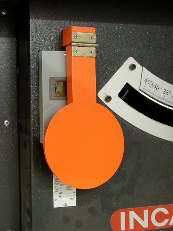
Important:  When you have the carriage complete, add a block of wood to the backside of the rear fence as shown in the second photo above.  The purpose of this block is to protect your fingers from the saw blade at the end of each cut.  The block must fully enclose the blade as it comes through the back of the fence.  You will need to notch the top corner of the block as shown to allow the carriage to slide freely back and forth.  Do not use the jig without this block in place.

To make the dial, click on the image above to open a .PDF file that contains a full sized image of the dial.  When you print the image, the diameter of the dial should be 3-1/2".  Paste the printed image onto a piece of 1/8" plywood (or something similar), cut out the circle, and drill a 1/4" hole in the center.  Next make a knob of some sort, and cut the lead screw to length from 1/4-20 threaded rod stock.  Attach the knob and the dial securely to one end of the lead screw.  The knob and the dial must not be allowed to rotate on the lead screw.

Next, thread the free end of the lead screw through the bearing and install a washer and a pair of jam nuts as shown in the photo nearby.  When you're using the jig, you'll need to apply slight pressure to the carriage to ensure that the jam nuts ride tight against the bearing.  If you want, you could add some sort of spring arrangement to take care of this automatically.

Finally, position the carriage over the rear fence and thread the lead screw into its embedded nut by turning the dial.  Check one last time that your saw can't cut into the lead screw, and you're ready to go.

Measuring Your Kerf Width

With the jig complete, you can now make precisely spaced crosscuts by clamping your workpiece to the carriage and then turning the dial to move the workpiece after each cut. Before you can do much of anything useful, though, you need to know the width of the kerf that's taken by your particular saw blade. If you have a dial caliper or one of those fancy electronic ones, this is fairly easy to measure, as follows:
  1. Use your saw to rip a piece of scrap two or three inches wide. Make sure the edges are both straight and parallel to one another, then use the caliper to take a precise measurement of the width of the scrap.
  2. Rip the scrap down the middle into two pieces.
  3. Reassemble the two pieces next to each other, and measure their combined width.
  4. Subtract the combined width of the two pieces from the width of the original piece. This difference is the width of the kerf that was taken by your saw blade.
If you don't have a caliper, you will have to take as good a guess as you can, then make some trial and error adjustments later when you actually go to use the jig.

Cutting a Simple Box Joint

Probably the simplest box joint to cut is one where the fingers are the same width as the saw kerf.  That would be roughly 1/8" for a normal blade, or whatever you want if you are using a dado stack.  In any case, the joint involves a series of cuts that are evenly spaced by twice the width of the saw kerf.  So let's suppose that your kerf is 0.132" wide.  That means you want to move the carriage by twice that amount, or 0.264", after each cut.  So how do you do that?

If you're a math whiz (or maybe a machinist), you might realize that each dot on the dial represents 0.002" of carriage movement, and that the numbers on the dial represent thousanths of an inch.  From that, you could figure out how far to turn the dial based on the numbers, but doing so would involve some error-prone arithmetic for every single cut.  Fortunately, there's an easier way that's based on the pattern of colored arcs and dots on the dial.

Here's all you have to remember:
  • Rotating the dial by one dot's worth moves the carriage 0.002".
  • Rotating the dial by one arc's worth moves the carriage 0.010"
  • Rotating the dial one full turn moves the carriage 0.050"
So, in our example, to move the carriage by 0.264", you would turn the dial five turns to move it by 0.250", then one arc to bring it to 0.260", then two dots to reach 0.264".  So "five turns, one arc, and two dots" is all you have to remember (or write down), and it's the same for every cut.  This is actually a lot easier to do than it is to explain.  Once you've played with it a while, you'll do it without thinking.

Cutting More Complicated Joints

With the jig, you're not limited to any particular finger width or spacing, although more complicated joints do involve a little bit of planning.  But the fundamental process is straightforward:  Figure out how you need to space your cuts, turn the dial to put the workpiece exactly (!) where you want it, and have at it.

Monday, October 10, 2011

Table Saw Kick-to-Stop Safety Switch

I’ve been meaning to make this thing ever since I got my table saw about three years ago. There’s a little pin on the back of the vertical piece that rides against the saw’s tiny stop button. So, by kicking the paddle with my knee, I can turn off the saw without having to look or fumble around for the little button. I figure it will be lots more convenient than the way it was. Heck, it might even save my bacon someday if I need to turn the saw off while both hands are busy trying to keep a workpiece under control.

I didn’t want to drill holes in my saw to mount the paddle, so I just stuck it on the cabinet with some 3M mounting tape. If the tape holds, I’m in business. If it doesn’t, then I’ll break down and drill a couple of holes for some bolts.

Made from scraps of poplar and 1/4” plywood. Tastefully finished with latex paint.

Saturday, August 27, 2011

Living Without an End Vise

My workbench is sort of a multipurpose table that I use for lots of different things. As a result, it doesn't have many of the features of a real woodworking bench.

For example, there are no dog holes, partly because there are drawers immediately below the top that would interfere with dogs and holdfasts, and partly because I really don't want to be dropping little parts through holes in the work surface when I've got the vacuum cleaner torn to bits for repair. Likewise, there is no end vise on my bench, because about half the reasons to have an end vise go away if there aren't any dog holes nearby.

"So," you ask, "what manner of ridiculous kludge do you use when you want to plane or scrape the surface of a long board?"

On the end of the bench where a real woodworker would have a real end vise, I arrange a thinnish board against end of the workpiece, a small wedge to push the thinnish board in the direction of the workpiece, and another board clamped to the bench to give the wedge something to bear against.

Then on the other end of the workpiece where a real woodworker would have a dog hole, I just clamp another thinnish board to the bench that the workpiece can butt up against. With all this in place, a quick tap of the wedge will secure the workpiece for almost any operation, and a quick tap in the other direction will release it.

Convenient? Not especially. Effective? Surprisingly.

Wednesday, August 24, 2011

Folding Step Stool - Free Plan

This is my take on a folding step stool design that's been around forever. My grandmothers each had one like it in their '50s kitchens. Today, fifty years later, you can point, click, and have a new one delivered to your door from any of a number of online vendors.

Many of these vendors describe their stools as "Amish". I'm not sure if that means the design is somehow Amish, or if the stools are being made by Amish builders, or what. In any case, they're pretty handy, and a heckuva lot safer than that upside-down Home Depot bucket you've been climbing on to reach the top shelf where Grandma keeps her gin.

Resources

If you want to build one of these yourself, the following two pictures link to drawings that give the basic dimensions for the stool:

The Stool
The Steps
Thanks to John Sprofera, you can also download a simple SketchUp model of the stool by clicking here.

There's also a more detailed SketchUp model here.  It shows the joinery in more detail, and has dimensioned drawings of all the individual parts.  This file contains the same set of drawings, but in PDF format if that's more convenient for you than SketchUp.

Construction Notes

I made my stool from oak, and finished it with several coats of wipe-on polyurethane. I used through mortise and tenon joints between the legs and the transverse stretchers, and floating tenons to join the legs with the side stretchers. I attached the seat and the steps with screws running up from underneath. These screws are set into oversize holes to allow the seat and the steps to expand and contract across their widths with changes in humidity. This precaution probably wasn't necessary for the steps because they are so narrow, but probably was for the seat.

Almost any wood would work for this project, although it might be a good idea to use a hardwood dowel for the step pivot, even if the rest was made from softwood. Likewise, any number of joinery options could work as well.

While there's nothing magical about this particular design, it is very important to get the shape of the side pieces that hold up the steps correct, as well as the location of the pivot pin. If you don't, the step assembly might hit one of the stretchers when it shouldn't. Be sure to keep this in mind if you decide to modify the plans for some reason.

The other thing to watch out for is the grain direction in the side pieces that hold up the steps. It's best to orient the grain as shown in the first picture above. Unfortunately, this makes it a little bit tricky to lay out the shape of these parts. To solve this problem, I made a full-size template out of 1/4" MDF. Then I traced around the template and cut out the parts slightly oversize with a band saw. Then I attached the template to the rough blanks one at a time and trimmed them to their final shape using a router with a flush trim bit.

Tuesday, August 16, 2011

Aurora Nightstand - Epilog

A couple of months ago when I started this project, I weighed the pile of rough boards that I thought I needed to make the nightstand, with the idea that I would then weigh the completed project to see how much of the original wood was left.

The original pile weighed about 61 pounds. The finished table weighs 29. So there you go.  About half of my mahogany went AWOL.  In the end, I had a couple of small offcuts that might be useful for something someday, but the bulk of the missing material wound up as sawdust and kindling for the barbeque.

Friday, August 5, 2011

Aurora Nightstand - Done!


With the drawer hung and the top and shelf mounted, this thing is done!  Big thanks go to Darrell Peart for such a beautiful design.  These pictures can do the rest of the talking:

Monday, August 1, 2011

Aurora Nightstand - Glue-Up

At last! Today was glue-up day. I started by gluing together the right and left sides as separate assemblies, but somehow failed to get any pictures of that. Here's the much more interesting final assembly, wherein many clamps were employed:


Even with the pads under the clamps, they messed up the finish a little bit. So one more coat of polyurethane is in order once I'm completely done with the remaining details like hanging the drawer and installing the shelf and the top.

Friday, July 29, 2011

Aurora Nightstand - Prefinishing

I applied stain (actually water-based dye) to all the parts last night, and the first few coats of wipe-on polyurethane today. More of the same to follow over the next couple of days. Then it will be time to glue this sucker together. Can't wait!


Wednesday, July 27, 2011

Aurora Nightstand - Ebony Plugs, Part II

I think today I must have set a new personal record for the most time spent per board foot of lumber processed. That's because I was finishing up the rest of the little ebony plugs that go on the nightstand legs. They're tiny, and making them was kind of tedious.


Instead of pounding them into the mahogany with a mallet like I was doing before, today I tried squeezing them in with a clamp. That worked much better. As long as they were in the hole straight to start with, the clamp made it very easy to push them in and to stop when they were at just the right depth.

Tuesday, July 26, 2011

Aurora Nightstand - Ebony Plugs, Part I

Today I finished up the rest of the ebony doodads on the top, then started on the plugs that go on the legs and the front of the drawer. Making the little plugs was easy enough, but I found it tricky to get them tapped into the holes at just the right depth. In fact, a couple of them were bad enough (too deep) that I removed them with a drill and a chisel and started over.

I'm wondering if squeezing the plugs into their mortises with a small clamp might be a more controlled process than trying to pound them in with a hammer. I think I'll try that on the next batch. With a total of 24 plugs in the legs and two more in the drawer front, there's no shortage of opportunity to practice.

Sunday, July 24, 2011

Aurora Nightstand - The Ebony Arrives

Hooray! The ebony finally arrived yesterday, and I had some time over the weekend to jump in and make the decorative splines for the nightstand top. The pictures show one of them. As luck would have it, the other three look about the same.

The ebony came in six pieces, each about an inch and a half square and about ten inches long. It was rough cut and covered with wax.

To make the splines, I used the jointer to get two edges on one of the ebony blocks flat and perpendicular to each other. Then I used the bandsaw to slice off a couple of 3/8 x 1-1/2 inch slabs, which I then cut down the middle to make the blanks for the four splines. Next, I routed the profile using the little jig I made the other day. Then I rounded off all the corners with files and sandpaper. I sanded the splines to 600 grit and then polished them up using white rouge (is that an oxymoron?) on a buffing wheel.

The ebony behaved itself with the jointer, the bandsaw, and the router. I got some tearout, though, when I tried to remove the bandsaw marks with a vintage Stanley 60-1/2 block plane. I'm guessing that a higher bevel angle on the plane iron would work better with the ebony. But at the moment I didn't want to get sidetracked into investigating that, so I switched to a disk sander for smoothing out the bandsaw cuts and adjusting the fit of the splines into their respective slots.

I'm starting to see how some people come to own a jillion hand planes.  Not that it could ever happen to me.

Thursday, July 21, 2011

Aurora Nightstand - Finishing Tests

Still no ebony. But today the shipment finally showed up in the USPS tracking system, so there's hope. I guess the eBay seller I bought it from was just a little poky in getting to the post office.

I really don't want to louse things up when it comes time to apply the finish on this thing, so I sanded up a few test boards for practice. For the stain, I used the mixture of General Finishes water based dyes recommended by Darrell in his article--seven parts orange and four parts medium brown. I put one coat of this dye mixture on half of each test board, and two coats on the other half. Then I wiped on five or six coats of thinned polyurethane according to the recipe in the Wood Whisperer's A Simple Varnish Finish DVD. Here are the results:


It's easy to see that the lightest board (the narrow one) needed the second coat of dye, but that two coats was too much on the darkest board. So the plan at this point is to apply one coat of dye to all the parts, and then put a second coat on the lighter ones only. I think this will give the best color match among the parts without going overbaord and making them all too dark.

Sunday, July 17, 2011

Aurora Nightstand - Yet Another Router Jig

Still no ebony.

When it finally shows up, I figure I'll want to make the biggest ebony pieces first. That way, if I mess them up, I may be able to make some of the smaller parts out of the ruined material.

So the biggest ebony parts are the decorative splines in the table top. Darrell's article suggests forming these by gluing the blank into the slot in the top, routing the profile in two steps with a flush bit and a couple of oversized bearings, and then rounding the corners over by hand with sandpaper to get the pillowing effect.

Yikes!  I don't like that idea at all, for lots of reasons:
  1. I don't have the necessary oversized bearings.
  2. With the splines glued in the slot in the top, I can't see how I would ever be able to round over their corners without marring the top itself.
  3. There'd be no way to polish the splines on a buffing wheel.
  4. If I messed something up, it might be really difficult to remove the glued-in spline without messing up the top in the process.
So I figured, why not rout the profile on the spline using a jig similar to the ones that were used to make the arched parts?  That way I can do the pillowing and buffing before gluing the spline into the top, and if I mess up a spline, I can just toss it and make another one.

So I tried it. The picture shows the jig, which clamps the part securely against a template with the required profile. After temporarily clamping the blank into the jig, I marked the curve on the blank and then cut away most of the waste using the bandsaw. Then I remounted the blank in the jig and routed the profile in one pass.


The picture also shows the result of the first test. The jig worked perfectly, but I didn't do the best job of getting the pillowing even, especially where the spline makes the little jog between the top and the breadboard end. I think I'll make another little scraper tool to help with that.

For the record, the test spline is made of ebonized mesquite, which means that I smeared some india ink on it, followed by a coat of gloss polyurethane.

Saturday, July 16, 2011

Aurora Nightstand - Completing the Drawer

Still no ebony.

But the drawer is almost done. About a year ago, Garrett Hack had an article in Fine Woodworking #213 about using solid wood instead of plywood for drawer bottoms. I had a little bit of poplar left over from a previous project, so I decided to try Garrett's ideas on the nightstand drawer. It was a little more work than just cutting out a chunk of plywood, but I really like the result.

I made another big departure from Darrell's plans by using some bamboo chopsticks instead of birch dowels to pin the big finger joints in the front of the drawer. I know, I know. I'm a wild man.

Friday, July 15, 2011

Aurora Nightstand - Oops #2

Oops. Yesterday I grabbed the shelf panel that I had carefully flattened a few days ago, and found that it had suddenly developed a really nasty cup. This was kind of a surprise to me. The wood had been stickered since I milled it about a month ago, and hadn't shown any signs of movement during that time.

Here's what I think happened: After flattening the panel, I put it up out of the way, lying flat on top of a sheet of plywood. Soon after that, the ambient humidity took a rather abrupt nosedive. So I'm thinking that the top surface of the panel, which was exposed to the hot, newly-dry air in my garage started to lose moisture. Meanwhile, the bottom surface couldn't dry out as fast because it was against the plywood. The direction of the cup was consistent with this fine theory.

The panel is now undergoing a three-step recovery program. (From what I hear, the twelve-step programs take a long time and involve lots of meetings. Nuts to that.) First, I set the panel up on some sticks so that air can circulate freely all around it. Then I dampened the concave side in the hope that it would reabsorb some of the moisture that it had presumably lost. That actually helped a lot. Finally, I applied some friendly persuasion in order to discourage further movement as the moisture content stabilizes.


I guess time will tell if this plan works or if I need to make a new shelf one of these days.

Tuesday, July 12, 2011

Aurora Nightstand - Archery, Part III

I originally thought that I would apply the finish to the main part of the nightstand, assemble it, and then build the drawer to fit. But I found myself waiting on the material for all the little ebony doodads, so I decided to go ahead with the drawer after all. The only critical step was making the drawer front fit properly within its opening, and I figured I could easily get the actual size of the opening by just dry clamping a few of the parts together.

The goal was to make the drawer front fit within the opening, with a 1/16" gap all the way around. I started by cutting the part about 1/4" too wide, and 1/8" shorter than the width of the opening. Then I cut the "ears" on the ends that mate with notches in the sides to form the giant finger joints in the front of the drawer. Then, using the ears as a reference, I aligned the part with the router jig I had made earlier and cut the bottom curve. Finally, I shimmed the part in the proper position within the opening, marked where the top edge needed to be, and trimmed it to its final width.

The next step was to complete the finger joints by cutting the rabbets and notches in the drawer sides. I did most of this on the table saw, with just a little bit of chisel work to make everything fit right.

Sunday, July 10, 2011

Aurora Nightstand - Some Loose Ends

With the shelf and top panels all glued up and flat, I figured I'd better take care of a number of pesky details that I had been neglecting. The first was to cut some little notches in the corners of the shelf to clear the legs. Darrell doesn't talk about these in his article, but they're definitely necessary.

Next, I chopped a few more mortises for the decorative plugs in the breadboard ends of the top. Once again, I did these by hand because they're relatively small and they need to have square ends. Besides, all this practice might come in handy someday if I ever need to cut a bunch of mortises by hand.

I did finally drag out my horizontal router table to cut the slots for the splines that align the breadboard ends with the top panel.


After attaching the breadboard ends to the top panel, I also used the horizontal router table to cut the long slots for the decorative spline details on the front and rear edges of the top. The horizontal router table wasn't really big enough to support the top panel, so I set up a temporary outrigger arrangement that made everything nice and stable.


You gotta love them C-clamps.

Thursday, July 7, 2011

Aluminum Bandsaw Table Insert

One of the guys over on the WoodTalk Online forum was complaining about the cheap plastic table insert in his bandsaw.  I had the same problem with mine some time ago, and solved it by using my wood lathe to make an aluminum replacement that fits better than the plastic one did, and is a lot less flimsy.

WARNING!!!  This article describes a procedure that might be considered outside the normal use of the tools involved.  If you elect to try this yourself, you are responsible for your own actions.  If anything described here doesn't seem safe to you, don't do it!

To begin, you'll need an aluminum blank that's at least thick enough to sit flush with the bandsaw table when the completed insert is installed.  Thicker is okay, but try to find stock that's as close to the correct thickness as possible.  Cut out a square of the material that's slightly bigger than the hole in the bandsaw table, and carefully mark two perpendicular center lines on it, as shown in the picture.

 Next, lay out the shape of the insert on the blank.  You can do this by scribing lines directly on the aluminum, or you can make a drawing on paper and glue it to the blank, as shown in the picture.  However you do it, be careful that the image of the insert aligns accurately with the centerlines you put on the blank in the previous step.

Find two small screws that you can use to secure the blank to a scrap of wood.  Then select a bit just slightly larger than the screws' diameter, and drill two mounting holes in the blank.  Place these holes in the area that will eventually be cut away to form the slot for the bandsaw blade.

Now mount a scrap of wood on your faceplate.

Install the faceplate onto the lathe, and if necessary, face off the outboard surface of the wood so it is smooth and flat.  With the lathe running, locate the center of rotation and use a pencil to place a small dot there.

Next, draw an arbitrary centerline through the dot.  Then rotate the scrap exactly ninety degrees and draw a second centerline perpendicular to the first one.

Now align the centerlines on the aluminum blank with the centerlines on the faceplate scrap, and attach the blank to the scrap with the two small screws.

You do NOT want to use your wood turning chisels on the aluminum!  Instead, grab an old file and grind a point on it similar to that shown in the picture.  You'll want this to be fairly small; mine is about 1/16" wide.

Now set the lathe to its slowest speed and use the modified file to cut a groove in the blank that's just outside the perimeter of the insert.  Make sure you're wearing eye and face protection, and go at it easy, with very light cuts.

Continue by making the groove deeper and wider until you finally cut completely through the aluminum and into the wood, leaving only the round insert mounted to the faceplate.

Use a normal turning chisel to remove some of the wood from around the outside of the blank, so that you can then use a regular file (with the lathe running) to clean up the edge of the insert.  Be careful at this point that you don't go too deep and hit the screws that are holding the scrap to the faceplate.

If you have an accurate way to measure the diameter of the insert, continue filing until you reach the correct size.  Otherwise, "sneak up" on the fit by repeatedly filing a little bit and then removing the faceplate from the lathe so you can test the size of the insert against the actual hole in the bandsaw table.

When you have the diameter correct, use the modified file to cut a little rabbet around the perimeter of the insert so that it sits flush with the table surface when installed.  Again, you may have to "sneak up" on a good fit by repeatedly removing a small amount of material and then checking the insert against the actual hole in the bandsaw table.

Now you can remove the insert from the face plate, cut out the slot for the bandsaw blade, and clean everything up with a bit of sandpaper.  This is what the top side of mine looks like.

And here's the bottom.